
In this walk-through, we’ll look at forming a hybrid cloud architecture utilizing an AWS VPC and a mock “On-Premise” site, connecting the two via a site-to-site VPN. In my first post on this topic (Part 1), we leveraged another VPC to mimic the on-prem environment utilizing a Cisco Cloud Service Router, linking the two via a AWS VPN Gateway and an AWS Customer Gateway. In this post, we’ll be performing the exact same actions on the AWS side; however, to mimic the “on-prem” side, we won’t use another AWS VPC. This time, we’ll use GNS3 on your local computer to form a site-to-site VPN from your GNS3 topology to the AWS VPC. In this setup, there are a few advantages. First, flexibility: you’ll be able to connect any topology you dream up in GNS3 to an AWS VPC to truly test out complex routing and switching connectivity. Second, lower cost for testing; in this case, you’ll only burn $0.05 per hour for the VPN connection in AWS, instead of $0.096 per hour for both the VPN and CSR running. So with that…
Dynamic “Hardware” VPNs using GNS3!
Upfront Warning: This lab will cost you money!
It’s not a lot, but if you leave the VPN connection associated, it could get expensive. Items in this lab which will cost you money are:
Site-to-Site VPN – $0.05 per connection-hour.
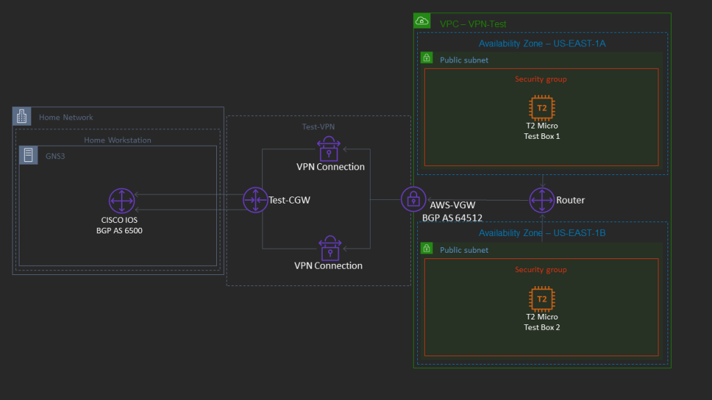
Although many of the steps within the procedure are a repeat of my AWS Networking Part 1, I’ll cover them in full again here for a consolidated walk-through. However, in this walk-through, our objective architecture looks something like this:
Prerequisites
Again, going into this lab, I’ll make an assumption you have a basic understanding of the AWS environment. With that understanding, there are a couple of prerequisite items which need to be configured prior to proceeding with the VPN configuration:
- A default VPC – Every AWS environment should have one of these; if you choose a custom VPC, that’s fine, but you’ll need at least one. This is the VPC from which we will create the VPN connection from, to your GNS3 environment. It would be preferable that any GNS3 topology which you will be connecting to this VPC does not contain any subnet CIDRs which exist in your AWS VPC.
- A GNS3 environment with a functional CISCO IOS Router – This router’s IOS needs to be capable of implementing IPSEC VPNs.
- A home internet router which supports NAT-T: This is NAT Traversal, which allows NAT’d IPs to traverse between IPSEC endpoints (encapsulated in UDP) and allow IKE and IPSEC to successfully negotiate. Since normally NAT modifies the IP header, this breaks IKE and IPSEC; NAT-T is designed to overcome this problem. Consult your home internet router’s documentation to ensure it supports this feature. Note: I previously had a Google Wi-Fi router which did not.
With these prereqs out of the way, let’s get started.
GNS3 Configuration
In my opinion, this is the most complicated part of this setup. In a nutshell, we’ll take a router within GNS3 and link it to the physical Network Interface Card of your workstation (whether that be a wired or wireless interface), and bridge it to your home/office LAN network. What this accomplishes is an interface within your GNS3 topology which can reach the Internet; more importantly, it’s an interface which can reach the AWS VPC in order to successfully setup a site-to-site VPN.
- Launch GNS3, and if you don’t have an existing project you can use, create a new one.
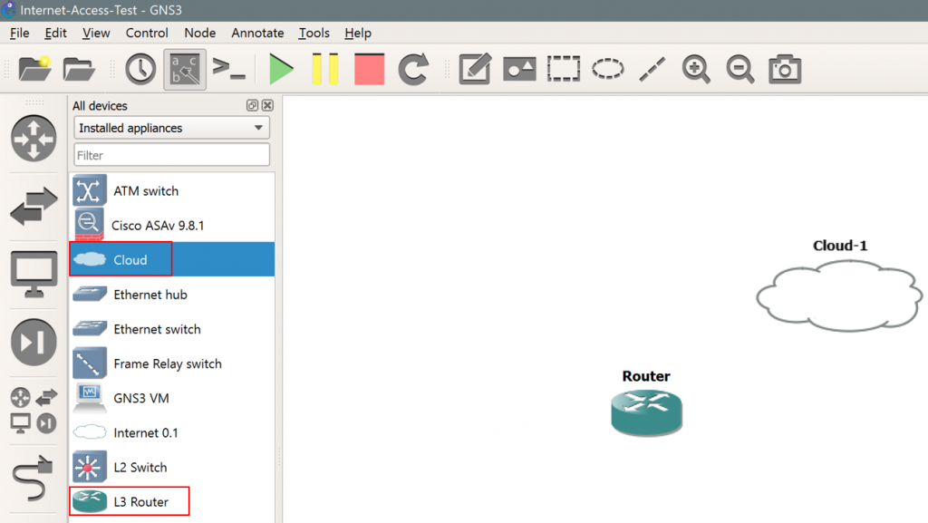
- Within the topology, ensure you have at least one router and one “cloud” device. Specifically, make sure this is “Cloud” and not “Internet 0.1”, as follows:
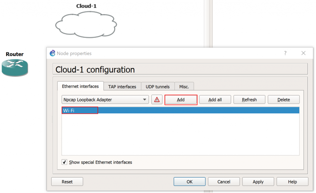
3. Next, right click on the Cloud icon and click Configure.
4. Under the “Ethernet Interfaces” tab, ensure the “Show special Ethernet interface” check box is selected.
5. This next step will depend upon which physical network interface on your GNS3 workstation is connected to the Internet. In my case, my Internet facing NIC is labeled “Wi-Fi” within Windows. Select the drop down menu and select the appropriate NIC for your workstation which provides internet connectivity, and click Add, as follows:
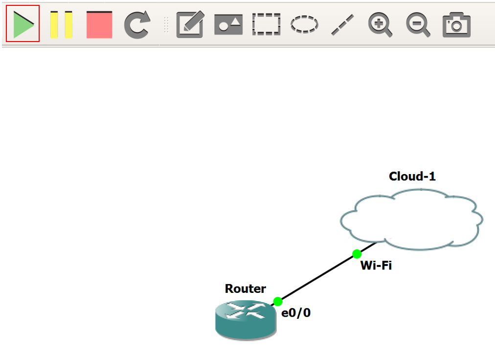
6. Next, connect the Router to the Cloud. Once connected, click the green Play icon, as follows:
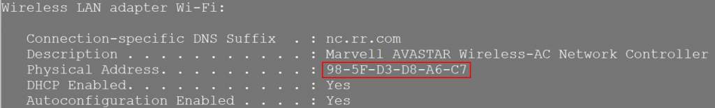
7. Before we make the required configuration changes on the router to get this working, there’s one piece of information we’ll need: The MAC address of your internet facing NIC card. Open a command prompt, and type ipconfig / all. Locate the internet facing NIC in the commands output, and copy its MAC address, as follows:
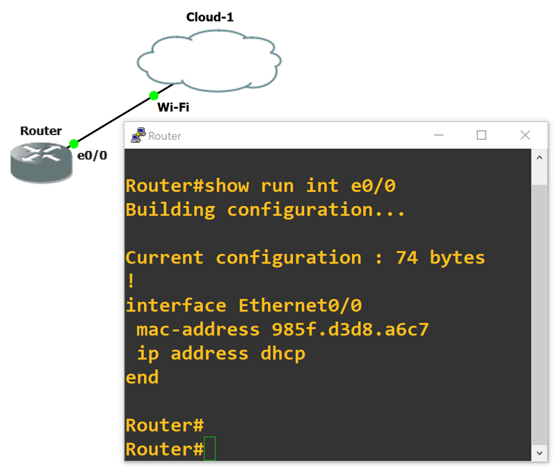
8. Next, we need to configure two items to get the router talking with the Internet: First is DHCP, for automatic assignment of an IP address on your local home network, and second the MAC address (which allows the DHCP process to negotiate an IP address.) Use the snippet below as a guide for configuring your own router, noting that a couple of items need to be updated. The MAC address needs to be the same as your workstations MAC (as noted above) and converted to dotted format, and the interface your configuring needs to be the one connected to the Cloud icon within GNS3. Here’s the example:
!
config t
!
 interface Ethernet0/0
  mac-address 985f.d3d8.a6c7
  ip address dhcp
  no shut
 end
9. If all went well, you should be able to ping 8.8.8.8 from your GNS3 router. If not, do not proceed to the next steps. First, ensure your router’s interface successfully receives an IP via DHCP, and the default gateway installs in the routing table as part of the DHCP parameters.
Customer Gateway
Now, we’ll configure the AWS side customer gateway which provides the interface into the AWS network from which to establish VPN connections.
- First, we’ll need to determine your public IP address. Head to whatismyip.com and look for “Your Public IPv4 is:” in the upper left portion of the page. Copy this address, as we’ll need it in the next few steps.
- Next, navigate to the VPC dashboard within the AWS console.
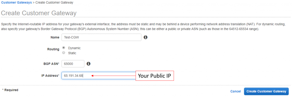
- On the page’s left hand menu, click Customer Gateway, and then the Create Customer Gateway button.
- Input the CGW’s name, ASN, and the public IP of the CSR instance (copied from the previous step.) For Routing, ensure to select Dynamic.
- Click Create Customer Gateway.
Virtual Private Gateway
Next, we’ll create the AWS side of the VPN connection.
- While still in the VPC dashboard, click Virtual Private Gateways on the left side menu.
- Click the Create Virtual Private Gateway button.
- Enter a name and ensure the Amazon default ASN is selected.
- Click Create Virtual Private Gateway to continue.
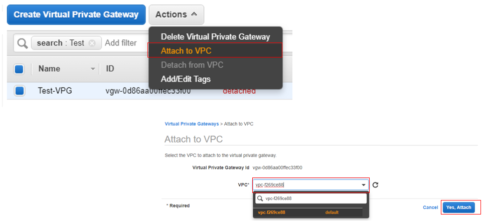
- Before we leave the VGW Dashboard, we must attach the VGW to a VPC. Select the newly created VGW, click Actions, and then Attach to VPC.
- The Attach to VPC page will load. Select the desired VPC, and then click Yes, Attach.
Site-to-Site VPN Connection
In this next step, we’ll configure the VPN parameters, linking the CGW and VGW.
- Also while still in the VPC Dashboard, click Site-to-Site VPN Connections.
- Click the Create VPN Connection.
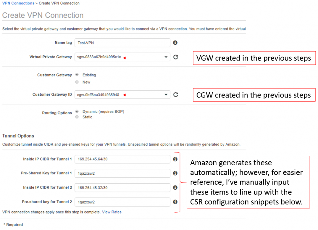
- Input a VPN Name and select the VGW and CGW created in the previous steps.
- For tunnel options, you can technically leave all of these fields blank; however, if you wish to utilize the router configuration snippets I provide below for the CSR, use the same pre-shared key, 169.254.45.64/30 for Inside IP CIDR for Tunnel 1, and 169.254.45.32/30 for Inside IP CIDR for Tunnel 2.
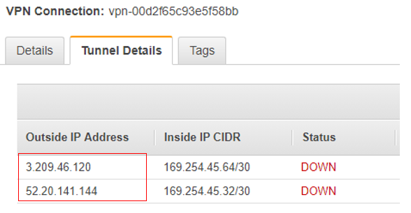
Note the AWS Outside IPs
Before we leave the VPC dashboard we need to ensure we’ve noted the outside IPs in use on the AWS end of the VPN connection. These are the IPs used to source the secure VPN tunnel on the cloud side of the connection, and will need to be input into the CSR configuration snippets to successfully build the VPN tunnel.
- In the VPC Dashboard, click Site-to-Site VPN Connections.
- Select the newly created VPN connection.
- Near the bottom of the screen, click the Tunnel Details tab.
- Write-down or take a screenshot of the outside to inside IP mappings, as shown in the screenshot below.
Enable Route Table Propagation
In order for routes to be dynamically propagated between the AWS VPC and the CSR, you’ll need to enable route table propagation.
- Within the VPC Dashboard, click Route Tables.
- Select the route table for the VPC attached to the VGW.
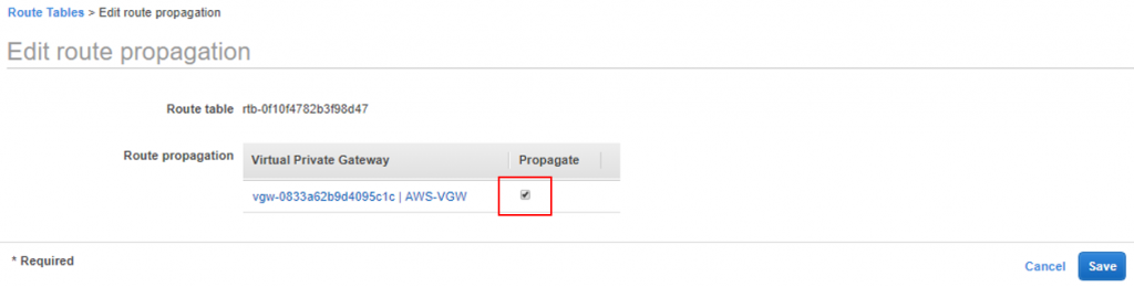
- Click the Route Propagation Tab on the menu near the bottom of the window, then click Edit Route Propagation.
- Select the check box under the Propagate column.
Final GNS3 Router Configurations
Now that all the AWS side VPN configurations are completed, we’ll move on to configuring the remaining guts of the GNS3 router. These are the last steps!
- Within GNS3, double click the router your performing the VPN connection from.
- Once successfully logged in, enter global configuration mode by typing config t, and then hit enter.
- We’ll use the snippet below to configure our router; before pasting this into the CLI, note the text in red; this needs to be updated with your own local interface and outside IP address (as noted in figure 9) mapped to tunnel one. Simply copy to a text editor and replace the instances of “OUTSIDE-IP-#1” with the full IP address and “Local-Router-Interface” with the actual interface of the router connecting to the Internet (in my case its Ethernet0/0.) Also note, this snippet is only for one of two VPN tunnels (the second tunnel configs are at the bottom of this post.)
!==================
!IKE Phase I Configs - Tunnel1
!===================
crypto isakmp policy 200
  encryption aes 128
  authentication pre-share
  group 2
  lifetime 28800
  hash sha
exit
!
crypto keyring keyring-vpn-01
  local-address Local-Router-Interface
  pre-shared-key address OUTSIDE-IP-#1 key 1qazxsw2
exit
!
crypto isakmp profile isakmp-vpn-01
  local-address Local-Router-Interface
  match identity address OUTSIDE-IP-#1
  keyring keyring-vpn-01
exit
!
!
!==================
!IKE Phase 2 Configs - Tunnel1
!===================
crypto ipsec transform-set ipsec-prop-vpn-01 esp-aes 128 esp-sha-hmac
  mode tunnel
exit
!
crypto ipsec profile ipsec-vpn-01
  set pfs group2
  set security-association lifetime seconds 3600
  set transform-set ipsec-prop-vpn-01
exit
!
crypto ipsec df-bit clear
crypto isakmp keepalive 10 10 on-demand
crypto ipsec security-association replay window-size 128
crypto ipsec fragmentation before-encryption
!
!
!==================
!Tunnel 1 Configs
!===================
interface Tunnel1
  ip address 169.254.45.66 255.255.255.252
  ip virtual-reassembly
  tunnel source Local-Router-Interface
  tunnel destination OUTSIDE-IP-#1
  tunnel mode ipsec ipv4
  tunnel protection ipsec profile ipsec-vpn-01
  ip tcp adjust-mss 1379
  no shutdown
exit
!
!
!==================
!BGP Configs - Tunnel1
!===================
router bgp 65000
  neighbor 169.254.45.65 remote-as 64512
  neighbor 169.254.45.65 activate
  neighbor 169.254.45.65 timers 10 30 30
  address-family ipv4 unicast
    neighbor 169.254.45.65 remote-as 64512
    neighbor 169.254.45.65 timers 10 30 30
    neighbor 169.254.45.65 default-originate
    neighbor 169.254.45.65 activate
    neighbor 169.254.45.65 soft-reconfiguration inbound
    network 0.0.0.0
  exit
exit
!
Verification
To verify everything is up and working, let’s start with the GNS3 router. Within the router’s CLI, make sure you are at Privileged Exec mode (it shouldn’t say “(config)” to the left of the # symbol; if it does, type exit.) Then type show crypto isakmp sa. You should see the following output:
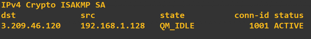
QM_IDLE is a good thing. If the output shows MM_NO_STATE under the state column, then phase 1 is failing, and you need to check the phase 1 portion of your configuration. Also, ensure you have a layer 3 path to the distant end address by pinging the “identity” address or outside IP on the AWS side.
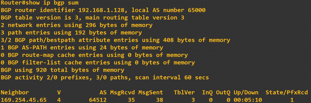
Next, type show ip bgp sum to list the BGP neighbors the router has established. In the output below, we can see that we currently have 1 neighbor, it’s been up for 5 minutes and 10 seconds, and 1 prefix (or route) has been received. If the state remains at idle or active, something is likely wrong with the tunnel interface or the BGP configuration.
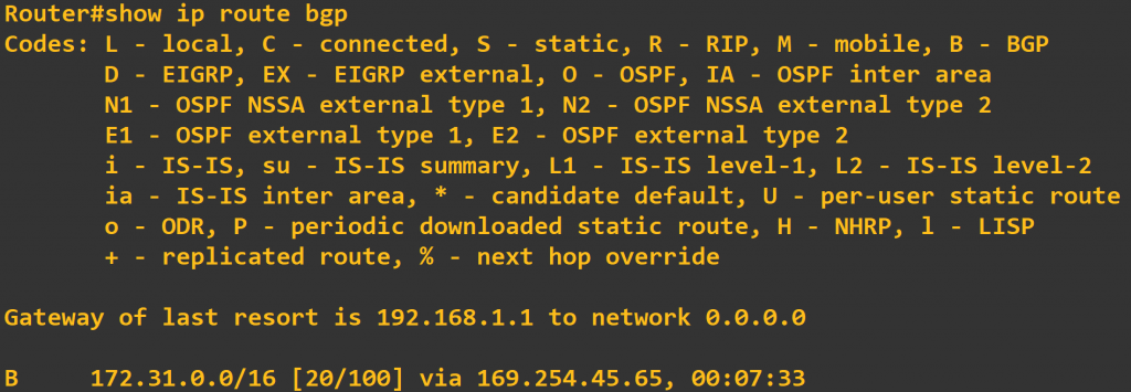
If we are BGP peers with the AWS VPC, we should also see some routes being learned from that peer in the route table, and according to the output above we are. To verify this, type show ip route bgp at the router’s CLI. In the output below, we are learning the 172.31.0.0/16 route via the 169.254.45.64 tunnel.
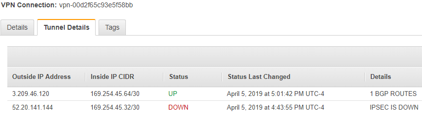
Now, check the AWS console to ensure it’s happy with the VPN.
- Go to the VPC Dashboard, and click on Site-to-Site VPN Connections.
- Select the newly created VPN connection, and then click on the Tunnel Details tab near the bottom of the window. Here you should see a status of UP for any tunnel you’ve configured on the CSR.
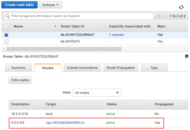
And last, we’ll want to check the routes being propagated into the AWS VPC router.
- Go to the VPC Dashboard, and click on Route Tables.
- Click on the route table associated with the VPC attached to a VGW.
- Then click the Routes tab near the bottom of the window. With what we’ve configured so far, we should see a default 0.0.0.0/0 route being advertised into the VPC from the CSR.
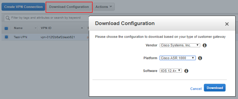
Final Notes
AWS Does provide somewhat customized configuration snippets for a variety of on-premise networking devices, for loading into your organic equipment. These configs contain a bunch of useful comments describing what each line of the configuration does, and what else can be modified, such as advertising additional networks. I recommend checking these out.
You’ll probably also note we’ve only done one tunnel configuration here so far and that the pre-canned configuration provided by AWS has two of everything: two phase 1 configurations, two phase 2, two tunnel interfaces, etc. This is for high-availability. Below is the second tunnel configuration to get both tunnels up and working.
Aside from configuring the remaining tunnel, we can now play around a bit. For example, we can add some regular Linux EC2 instances to the VPC and test reachability from the GNS3 router (but keep in mind security groups will probably need to be modified to allow inbound traffic to those instances from the GNS3 router.)
Remaining Configs (Tunnel 2)
!==================
!IKE Phase I Configs - Tunnel2
!===================
crypto isakmp policy 201
  encryption aes 128
  authentication pre-share
  group 2
  lifetime 28800
  hash sha
exit
!
crypto keyring keyring-vpn-02
  local-address Local-Router-Interface
  pre-shared-key address OUTSIDE-IP-#2 key 1qazxsw2
exit
!
crypto isakmp profile isakmp-vpn-02
  local-address Local-Router-Interface
  match identity address OUTSIDE-IP-#2
  keyring keyring-vpn-02
exit
!
!==================
!IKE Phase 2 Configs - Tunnel2
!===================
crypto ipsec transform-set ipsec-prop-vpn-02 esp-aes 128 esp-sha-hmac
  mode tunnel
exit
!
crypto ipsec profile ipsec-vpn-02
  set pfs group2
  set security-association lifetime seconds 3600
  set transform-set ipsec-prop-vpn-02
exit
!
crypto ipsec df-bit clear
crypto isakmp keepalive 10 10 on-demand
crypto ipsec security-association replay window-size 128
crypto ipsec fragmentation before-encryption
!
!
!==================
!Tunnel 2 Configs - Tunnel2
!===================
interface Tunnel2
  ip address 169.254.45.34 255.255.255.252
  ip virtual-reassembly
  tunnel source Local-Router-Interface
  tunnel destination OUTSIDE-IP-#2
  tunnel mode ipsec ipv4
  tunnel protection ipsec profile ipsec-vpn-02
  ip tcp adjust-mss 1379
  no shutdown
exit
!
!
!==================
!BGP Configs - Tunnel2
!===================
router bgp 65000
  neighbor 169.254.45.33 remote-as 64512
  neighbor 169.254.45.33 activate
  neighbor 169.254.45.33 timers 10 30 30
  address-family ipv4 unicast
    neighbor 169.254.45.33 remote-as 64512
    neighbor 169.254.45.33 timers 10 30 30
    neighbor 169.254.45.33 default-originate
    neighbor 169.254.45.33 activate
    neighbor 169.254.45.33 soft-reconfiguration inbound
    network 0.0.0.0
  exit
exit
!